

PLCC Components
Wave Traps
The wave traps direct carrier energy on transmission line towards remote line terminals and not towards the station bus; thus isolating it from bus impedance variations. Wave trap is usually a form of a parallel resonance circuit which is tuned to the carrier energy frequency.
A parallel resonant circuit has high impedance as its tuned frequency, this causes most of the carrier energy to flow towards the remote line terminal. Wave trap coil provides a low impedance path for flow of power frequency energy. Since power flow is rather large at times, the coil used in a wave trap must also be large physically.
Once carrier energy is on the power line, any control of the signal has been given over to nature until it reaches the other end. As it travels to the other end, the signal is attenuated and noise from environment is added it. At the receiving terminal, the signal is decoupled from power line in much the same way as it is coupled at the transmitting terminal. The application of each component of the PLC channel must be considered carefully for system to operate properly.
Various Blocking Bands in line trap:
- Single-frequency tuning
- Damped single-frequency tuning
- Double-frequency tuning
- Wide-band tuning

Design & Construction – Line Trap
1. Main Coil
Quality Power designs and manufactures Line Trap main coils that carry rated power frequency current and withstand higher fault levels of sub-station equipment. The line traps manufactured resin-encapsulated design for high mechanical strength of the winding.
Other features include:
- Rugged Construction as per IEC 60353
- Dry Q Coil Technology
- Self resonant frequency >500KHz
- Class F Insulation
- Lowest losses
- Low Temperature stress
- Compact Dimensions & Adaptable Mounting Features
- Lower weights
- Silicon coated RTV resin coat
- Coated with UV resistant special polyurethane paint
2. Tuning Device
Tuning device is connected in parallel with main and protective device. It forms a band-stop filter in conjunction with the inductance of the mail coil. This also ensures that the line trap offers high impedance to carrier currents under all conditions including resonance. The tuning device can either be single-band tuned or have multiple bands. Tuning circuit device is made of several combinations of capacitors, resistors, and inductors connected in series or parallel of comparative low power ratings. The tuning circuit is enclosed in weatherproof enclosures filled with resin/foam.
- High quality Tuning components
- High frequency performance
- Resin encapsulated
- Dielectrically tested
- Ability to withstand High Temperatures
- Multiple Tuning in single pot
- Compact and sturdy
3. Protective Device
- IEC 60099 compliant
- Transient Overvoltage Protection
- Polymeric construction
- Light & Compact
Protective device ensures protection of tuning device and main coil against surge voltages. Proper insulation coordination between mail coil insulation level and the surge arrestor characteristic is achieved to ensure reliable protection. The lightning arrester can be polymer-housed gapless or gapped type.
Quality Power provides Line Traps equipped with Metal oxide lightning or surge arrestor
4. Bird Barriers
Bird barrier is provided as an accessory for protection against birds and environment.
a. Terminal Holes Pattern
Standard 4-hole NEMA flat aluminum terminals are provided which is customizable as per requirements.
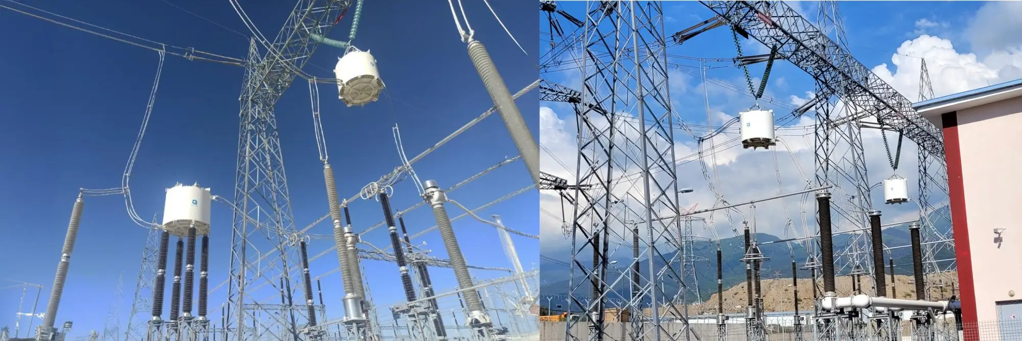
b. Mounting of Line Traps
Quality Power Line Traps are configured with number of mounting options as follows:
- Pedestal Mounting
- Tripped Structure Mounting (BPI Mounting)
- Suspension mounting
- CVT Head Mounting
- Horizontal Mounting
Accessories-Quality Power generally provides the Line Traps with following accessories either Mandatory/Optional on request.
- Bird Barrier (Mandatory/optional)
- Suspension Pins (Mandatory/optional)
- Pedestal (Mandatory/optional)